Advanced Rocketry
This section presents some of the more advanced rocketry information you will need to move further in the hobby. The material presented is also covered on the S.T.A.G.E.R. Advanced Rocketry Quiz.
Model Rocket Stability
|
The centre of gravity of a model rocket is the average location of the weight of the rocket. It can easily be determined by finding the balance point of the rocket. This can be done using a looped string held from above around the Cg or by balancing the rocket on a ruler at the Cg. The centre of gravity of a model rocket is typically shown graphically with the symbol is shown to the right.
|
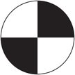
Centre of Gravity
|
|
The centre of pressure of a model rocket is the point through which all the aerodynamic forces on the rocket act. Because model rockets are fairly regularly shaped, a simple method of calculating the Cp of a rocket is to make a cardboard cut-out of the projected area of the model and find its balance point, just as with the centre of gravity. The symbol for centre of pressure is shown to the right.
|
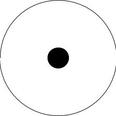
Centre of Pressure
|
The Barrowman Method for calculating centre of pressure was developed in 1967. For those interested, a detailed approach to using this method can be found here.
For a model rocket to be stable and fly safely, its centre of gravity must be ahead of its centre of pressure. A rocket whose centre of gravity is ahead of its centre of pressure by a length equal to the rocket's diameter is said to have one caliber of stability. This is typically the minimum caliber of stability for a successful, safe flight.
For a design that is unstable, several modifications could be made, including:
For a design that is unstable, several modifications could be made, including:
- adding weight to the nose of the rocket
- making the rocket longer
- moving the fins back
- enlarging the fins
There are three axes of rotation for a model rocket. The first is the roll axis, which is a line from the tip of the model's nosecone through its centre of gravity to the centre of the nozzle exit. Careful alignment of fins will prevent motion around the roll axis. The second axis is perpendicular to the roll axis through the centre of gravity, called the pitch axis. An unstable rocket may rotate end-over-end vertically around the pitch axis. The yaw axis is perpendicular to both the roll and pitch axes and also extends through the centre of gravity. An unstable model may rotate sideways through the yaw axis.
Even a stable model will experience slight rotation around the pitch and yaw axes, however, it will be able to quickly recover and swing back into a more desired orientation. An unstable rocket will not be able to recover and results in an unsafe flight.
Even a stable model will experience slight rotation around the pitch and yaw axes, however, it will be able to quickly recover and swing back into a more desired orientation. An unstable rocket will not be able to recover and results in an unsafe flight.
There are several pieces of software that can be used to design stable rockets and predict their centres of gravity and pressure.
Open Rocket, Rocksim, and SpaceCAD are three of the most popular.
Open Rocket, Rocksim, and SpaceCAD are three of the most popular.
Weather Cocking
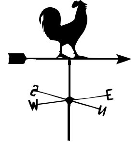
Weather Cock
|
Weather cocking describes the phenomenon whereby the model rocket tilts into the wind, reducing its maximum altitude because of a non-vertical flight. In the absence of any wind, the effective flow direction of the air surrounding the rocket is vertically downward as the rocket pushes upward. In the presence of a horizontal wind, the effective flow direction of the air around the rocket becomes the vector sum of the wind velocity and the velocity of the air moving relatively downward against the model. This causes the model to rotate around its centre of gravity into the wind until it is aligned with the effective flow direction. A higher wind velocity and a slower model velocity will cause the angle at which the rocket will tilt to become greater
|
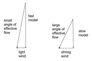
Weather Cocking
|
Engines and Thrust Curves
|
A model rocket engine consists of the following parts:
|
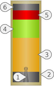
Model Rocket Engine
|
Once a model rocket engine is ignited, the propellant (3) burns for a short time, usually less than one second. This gives the rocket its initial thrust. Once the propellant has been exhausted, the model continues to coast while the delay element (4) is burned. The delay does not provide more thrust, but rather lets the rocket continue coasting until it reaches apogee, at which time the ejection charge (5) is fired, causing the recovery device to be deployed. It is important to understand how engines work so that the proper thrust and delay can be selected for each model.
|
Each model rocket engine is named using a letter and two numbers. The letter represents the range of total impulse that the engine provides. The first number represents the average thrust provided by the engine over its burn time. The second number represents the delay time, in seconds, between the end of the propellant burning and the ejection charge firing. (See Beginner Rocketry for more information.)
|
Thrust:
Impulse:
|
Engine Weights:
|
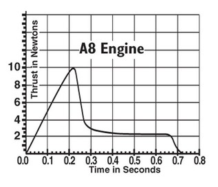
Thrust curve for an A8 engine
|
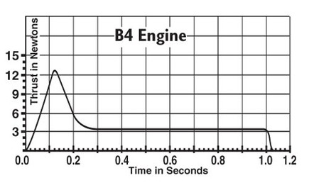
Thrust curve for a B4 engine
|
Two thrust curves are illustrated above; one for an Estes A8 engine and the other for an Estes B4 engine. The A8 engine produces a maximum thrust of about 10 N at 0.2 s after ignition while the B4 produces over 12 N of thrust after about 0.12 s. The A8 engine then continues to provide a little over 2 N of thrust until burnout at 0.7 s while the B4 engine provides 3 N of thrust until about 1.0 s.
|
Multi-Staging
Multi-staging is a method of igniting two or more engines in series in a single rocket. The first engine is housed in a booster section (body tube and fins) that falls from the rocket and tumbles to the ground when the ejection charge fires. The booster engine has no delay between burnout and ejection. Its ejection causes the engine in the next stage to ignite. This next stage can be a second booster or the main, sustainer part of the rocket.
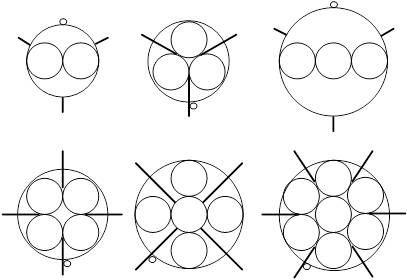
Clustered Engines
Engine clustering is a method of igniting two or more engines simultaneously in a single rocket. All engines in a cluster are typically of the same type so that ejection occurs simultaneously. It is important to wire the igniters for all the engines in parallel so that all engines ignite at the same time. Sometimes a clip whip is used to help connect the igniters. A clip whip has two wire leads at one end to connect to the launch system and two, three, or four sets of clips at the other end to hook up the igniters.
Recovery Techniques
Some common recovery techniques are:
- tumbel
- streamer
- parachute
- helicopter
- glide
Finishing Techniques
Finishing a rocket can be the most difficult part of a build, but it can also be the most rewarding. Some common techniques to help achieve a great finish are:
- filling body tube spirals
- filling grain on fins
- priming
- painting
